Automated Pallet Unlocking System in Tow Vehicles
Vignesh
12 00 AM ,Wed, Apr 01 2015
Problem Satement
The parts supplied by vendor companies in the assembly plant reception area are to be taken to the corresponding assembly points. This is done with the help of tow trucks which are used to carry the trolley pallets loaded with parts to the concerned assembly lines. The truck driver has to manually step down from the vehicle to lock the pallet to the truck and has to do the same while unlocking the pallet. So, in order to increase the operation effectiveness and to reduce feed time and driver fatigue, automated pallet unlocking system is proposed to overcome the shortcomings. In fact, it is one of the benchmark points of Hyundai Motor India Limited.
Project Scope
There are two types of tow trucks used in assembly #2 plant of which 19 are Line P30 trucks and 4 are Jost trucks. The automated pallet unlocking system could be implemented in both these tow trucks. However, because of their large number LindeP30 trucks are chosen for implementation. Also, the length of Linde trucks is greater than that of Jost trucks thus making the unlocking operation even more difficult and time consuming.
Design
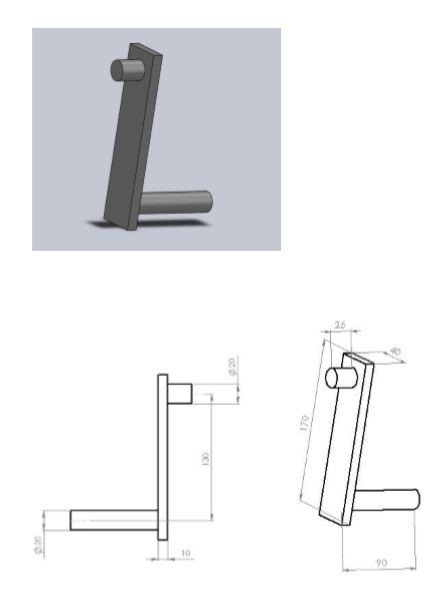
The design of each and every component of the Pallet Unlocking System is modeled using ‘PRO-E’ software after initial calculations, based on which the dimensions are fixed. The material ‘Mild Steel’ is chosen for making the components due to their abundant availability within the industry and also due to its strength and reliability. The separately modeled components are then assembled using the software ‘Solid Works.’
The ‘Scotch Yoke’ mechanism is chosen over various other mechanisms owing to its high linear velocity, simplicity and robustness. There is a frame that is designed according to the dimensions in the rear portion of the tow vehicle where the system is to be placed. The design of the plate too is made in PRO-E so as to accommodate the system. The frame is made using the scrap material that is used in cases that carry KD parts.
Final overview of the design is obtained by assembling the individual components together. The initial and final position of the key during various degrees of rotation of the crank is also shown.
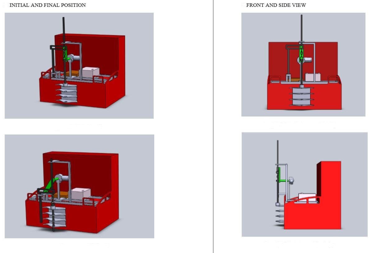
Initial&Final Posistions, Front&Side Views
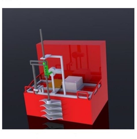
Isometric view of the Setup
Fabrication of Parts
The various parts fabricated are listed below:
- FRAME
- MOTOR SHAFT
- CRANK
- YOKE
- PROTRUTION
- GUIDE ROD
- KEY WITH CHAIN LINK
| Type of Work | Machine Used |
|---|---|
| Cutting plates | Band saw |
| Grinding | Horizontal axis grinding machine |
| Welding | Arc welding equipment |
| Electrode size | 3mm |
| Holes on the plates | Radial Drilling machine |
| Milling on the plate to produce slots | Vertical Milling machine |
The components are separately fabricated by above mentioned operations. A Pillow block is used to support the shaft and take up bending and tensile stresses.
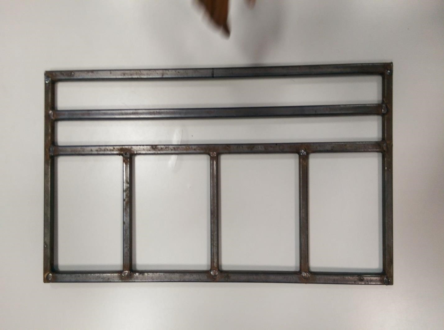
Frame Used for Motor Mounting
The frame is made out of rectangular square tubes which are sent out as scrap. There are various slots provided in the frame to accommodate battery, motor stand, guide rods etc.
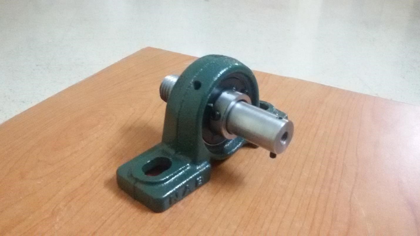
Shaft with Pillow Block
Crank
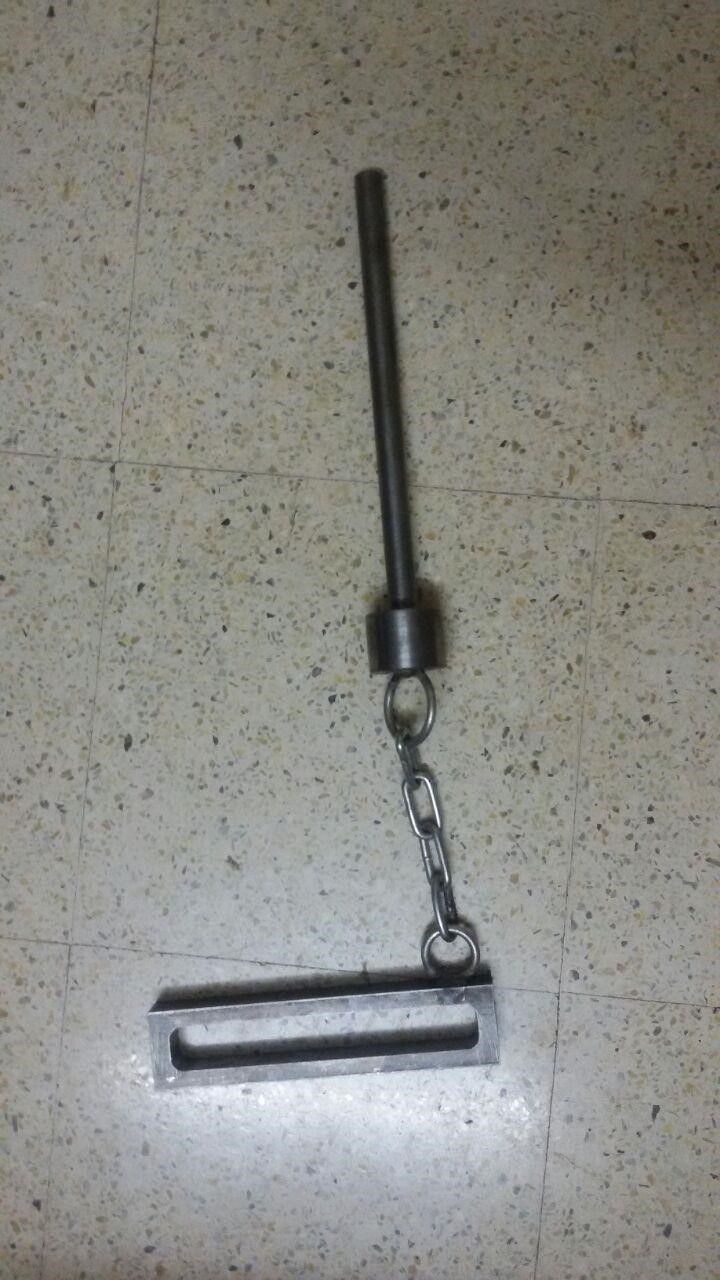
Yoke with chain link
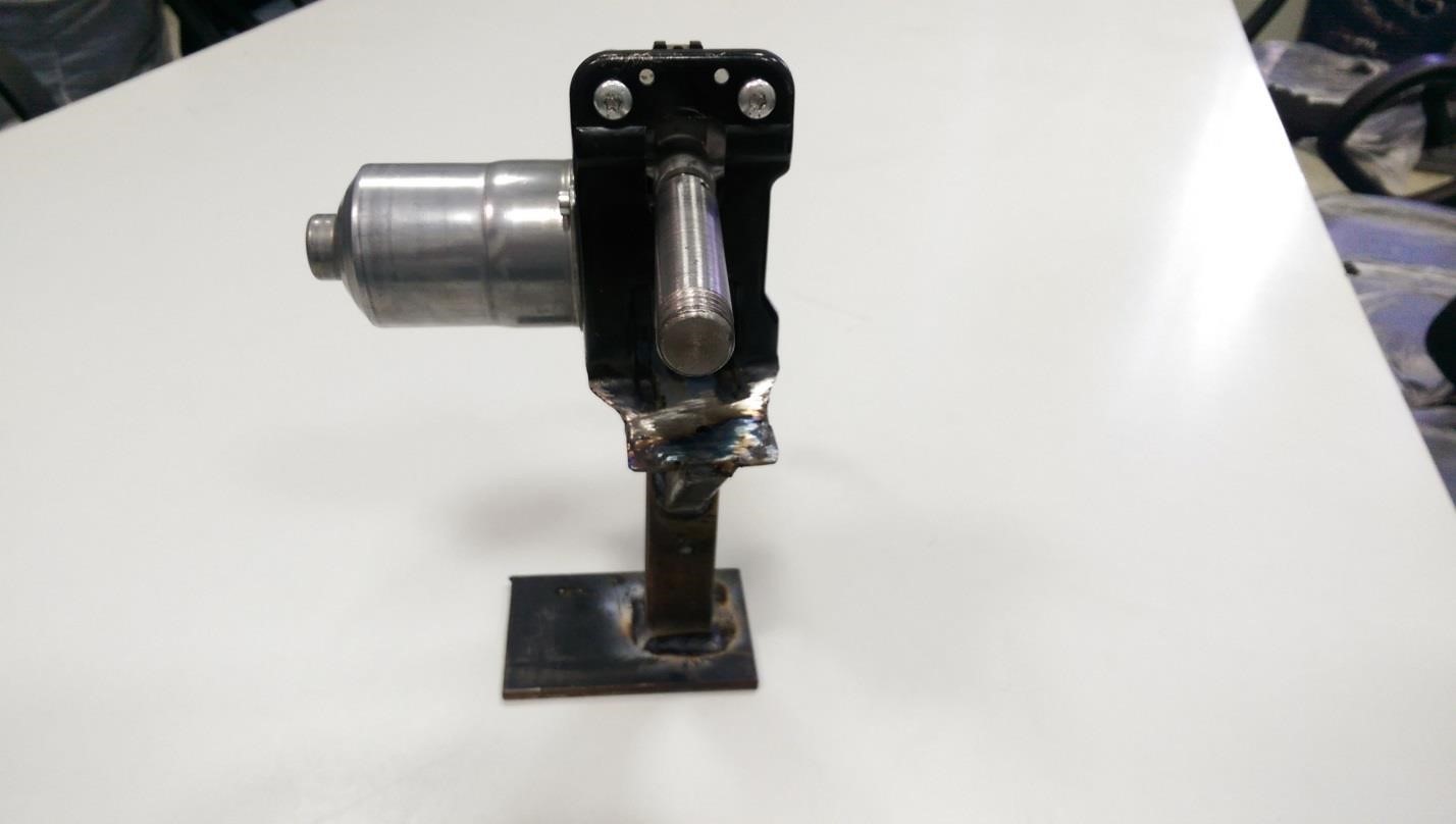
Motor mounting front view
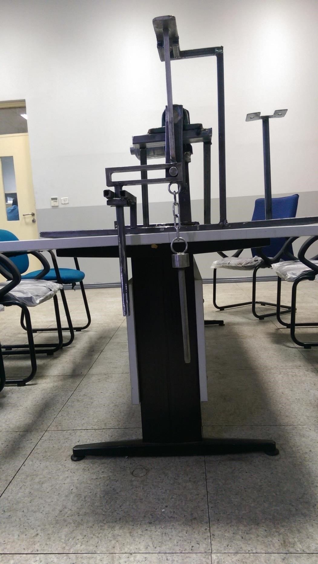
Complete assembly of the setup
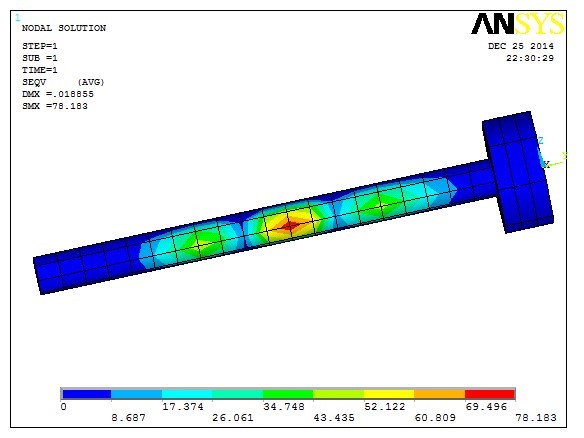
Key Deformation Analysis:
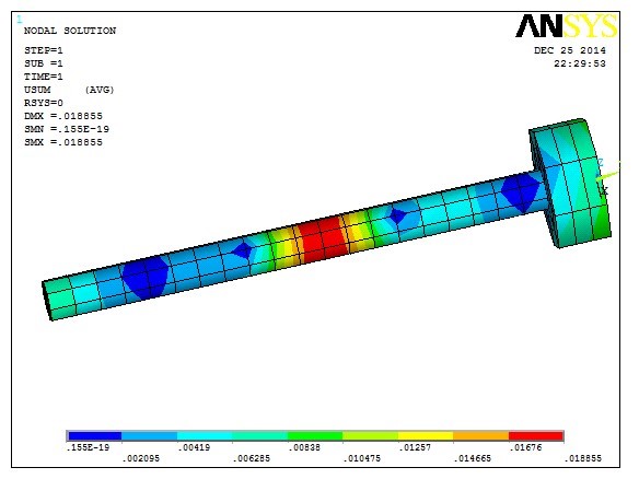
The above figure shows the deformation in various parts of the key due to the application of a tangential load.
The below analysis was done using the ANSYS software that shows the stresses induced in various portions of the key due to tangential loading.