Overview
“The unscientific procedure employed during assembly of femoral head over the stem”. This results in application of less or more force than 4.5 ± 0.5 KN. It leads to loosening of femoral head or head/stem interface damage.
Proposed solution & Design Objective / Criteria
We propose an Automatic-Hammer to ensure application of 4.5 ± 0.5 KN force on the femoral head during assembly over stem. The design objectives of the automatic hammer are:
a. It must ensure application of 4.5 ± 0.5 KN of impact force
b. It should provide force feedback
c. It should be usable with different femoral head sizes (viz. 28 mm, 32 mm, 36 mm diameter)
d. It must be able to be sterilized
Auto-Hammer Design
The auto-hammer is designed using Solidworks package. The auto hammer consists of mainly five parts:
a. DC motor and planetary gear system
b. Rack and pinion
c. Spring, and,
d. Impulse hammer
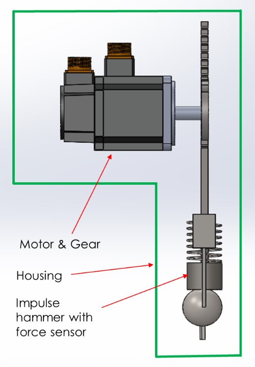
The Auto-Hammer is enclosed inside a gun like housing with a pistol grip form (Refer figure 4). The femoral head is temporarily held with the help of removable lower casings that come in various sizes to meet the design criterion of accommodating different femoral head diameters. The other reason for including a removable casing is to ensure sterilizability prior to use for every patient. A spring of high stiffness (refer section 5 for spring design) is attached to the fixed upper casing. An impulse hammer is fastened permanently to the rack which is driven by the pinion. The rack passes through the center of the spring and the hole provided in the upper casing. The impulse hammer is designed to have a larger diameter that prevents it from moving up through the hole in the upper casing. The motor housing includes the planetary gear system that can deliver high torque output.
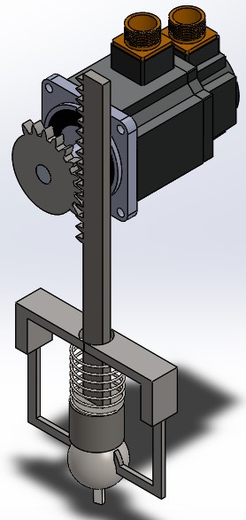
Isometric View of Auto-Hammer
Auto-Hammer Mechanism
A compact DC Motor with planetary gear system for high torque output is connected to a pinion of 2 cm diameter. The pinion drives the rack with the help of the torque provided by the gear. The impulse hammer along with the rack is lifted because of the rotation of the pinion. The impulse hammer compresses the spring in the process. There are only limited teeth cut on the pinion which depends on the length (10 cm) up to which the rack needs to be lifted or the linear distance up to which the vertically mounted coil spring needed to be compressed. Once the spring is compressed to the desired distance the pinion will start to disengage with the rack. As the pinion disengages with the rack, the impulse hammer along with the rack is pushed down because of the spring force. A coil spring of appropriate stiffness and length (refer section 5 for spring design) is chosen to achieve the required impact force. Hence, the impulse hammer imparts the desired impact force on the femoral head which is now assembled to the trunnion because of the blow. The feedback mechanism which is a part of the impulse hammer provides the force feedback when it impacts the femoral head. The rotation of the motor is also controlled with the help of a microcontroller for precise control.

Front View of Auto-Hammer
Spring Design
We will use a helical spring in our design to achieve the impact force of 4.5 ± 0.5 KN. We know, the amount of force derivable from spring is proportional to the amount of compression or extension along the axis of the spring and the axial stiffness of the spring. For our design, we have fixed the design envelope of the assembly Automatic-Hammer. Once the tool length is fixed, we derived the required spring stiffness. The length of the Automatic-Hammer has been fixed to 40 cm. Thus, the spring with stiffness value of 45 N/mm will be used in our Auto-Hammer to achieve 4.5 ± 0.5 KN of impact force.
Side View of Auto-Hammer
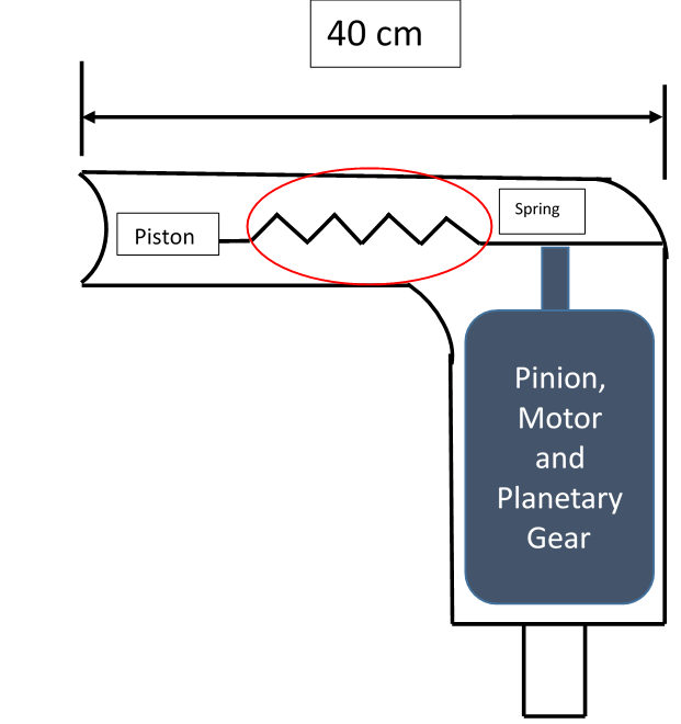
Representative figure displaying the design envelope of the Auto-Hammer
Torque output at gear shaft
As shown above and in the Auto-Hammer mechanism, in order to achieve the output force of 4.5 ± 0.5 KN at the spring, we need to extend it using a rack and pinion mechanism which is driven by the motor and planetary gear system. To move the rack by 10 cm, we need to provide fixed amount of torque at the gear shaft and in turn at the pinion. Again, we will fix our design space and take the maximum distance (also the moment arm) between the rack and the pinion center as 2 cm. Thus, the toque output required at gear shaft to ensure 4.5 ± 0.5 KN of force is 9000 Nm.