Overview
Airflow inside the airway tree is an important factor in the studies of pulmonary acoustics, disease studies and particle deposition inside airways. But measurement of airflow inside airways is challenging due to accessibility at different location of the tree for its geometry. Hence the results obtained in these measurements might not be accurate. The project will discuss the experimental setup for measurements of airflow and acoustics inside the airways
Calibration
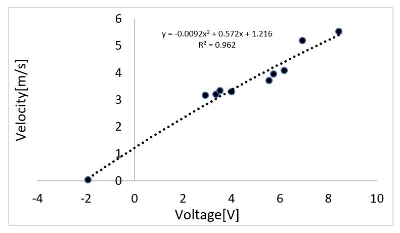
Calibration of pressure transducer using hot wire:
•Hot wire was used to calibrate the pressure transducer using the flow source of the experimental setup
•The velocity vs voltage was found to be related in a quadratic relation
•The velocity profile of the flow source was measured by hot wire from the top edge to the bottom edge
•The entrance velocity profiles were found to be relatively flat with a little bit of high velocity towards the edge
Airflow velocity distribution at the source
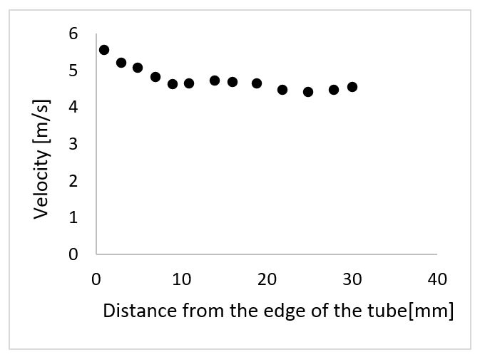
Velocity profile measurement using hot wire at different vertical distance from the edge of the tube
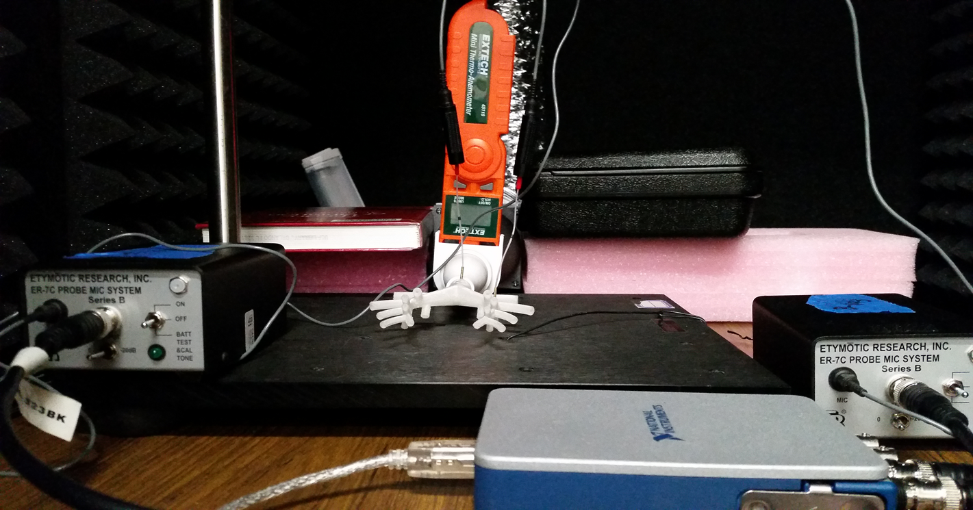
Calibration of probe microphone:
•Probe microphone was calibrated using the signal conditioner unit which generated a 1 kHz 94 dB signal.
•The generated signal was recorded using the probe microphone.
•The output of the microphone was visualized in an oscilloscope. Figure below showed the resulting output signal showed good agreement with the manufacturers standards (within 40mV-60mV).
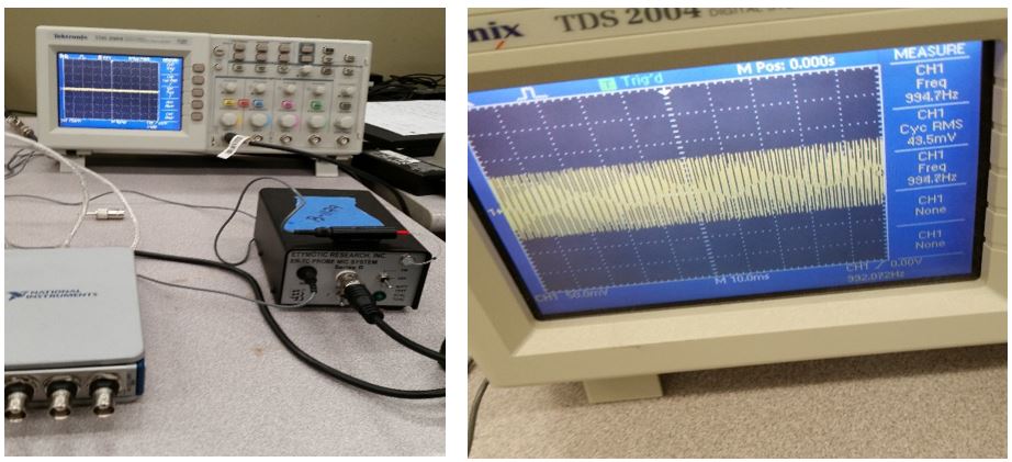
Calibration of probe microphone (Left): Probe microphone is connected to the calibration port of the signal conditioner unit. (Right): Microphone output is plotted in an oscilloscope.
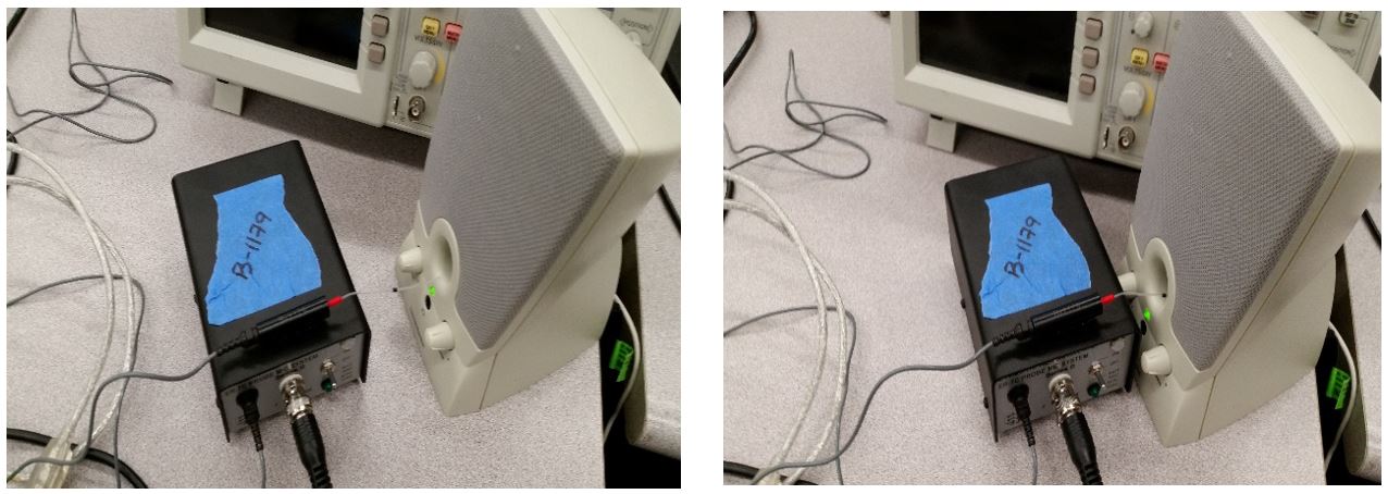
Probe microphone is placed at a distance of 80 mm (Left) and 40 mm (Right) from the speaker
Velocity profile at the entrance
•A Pitot tube and pressure transducer setup was used to measure velocity profile at the exit of the contraction
•The velocity profile of the flow source (at the exit of small contraction) was measured by the pitot from one edge to the other edge in horizontal and vertical directions
•The figure below shows that the Vertical and horizontal velocity profiles at the entrance of the airway model is predominantly flat
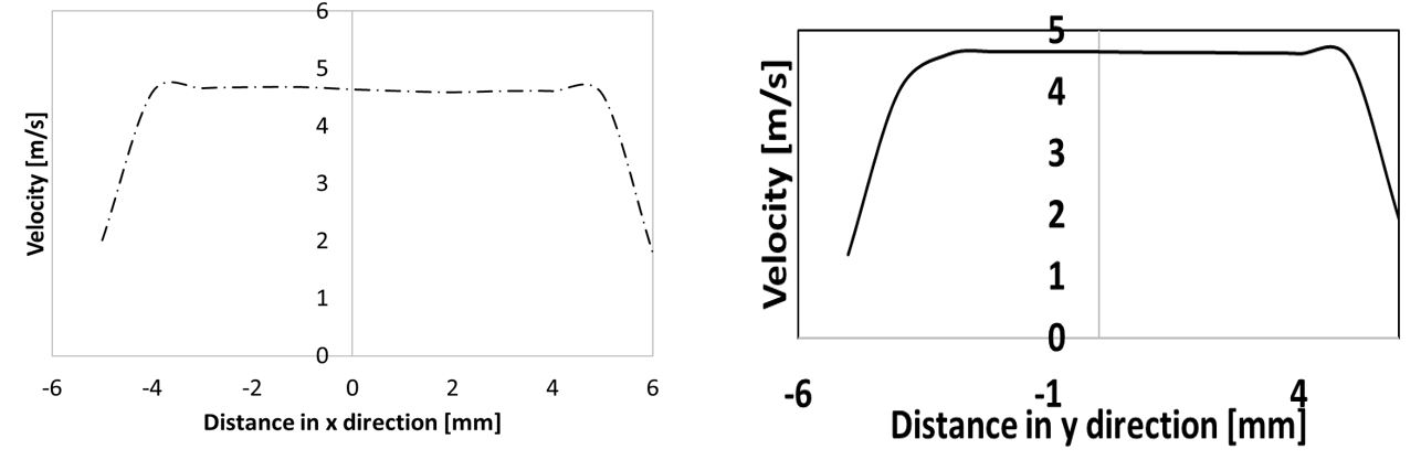
Velocity profile at the exit of small contraction
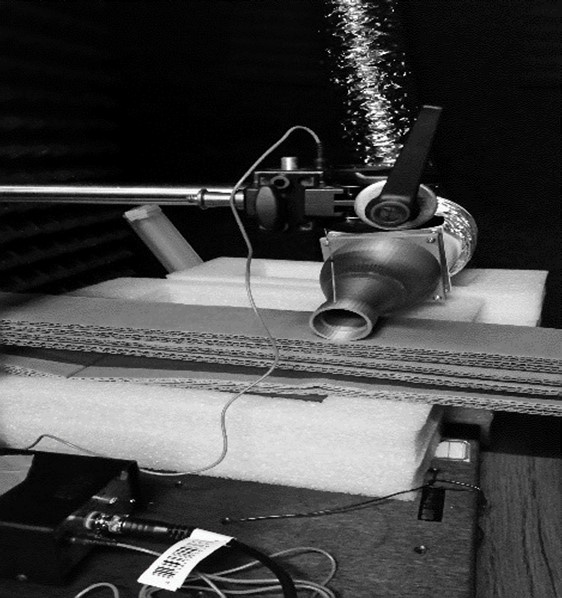
Miniature model of a pig airway:
•A miniature model of airway tree was used to measure static pressure at the trachea
•The miniature model of the airway tree had smaller branch diameters
•This allowed the model to have high-pressure difference compared to large diameter models which can be measured by the pressure transducer of the setup
•A small connection was made at the trachea for connecting pitot tube and microphone to measure the pressure and the sound generated at the location respectively
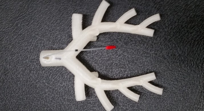
The miniature pig airway tree
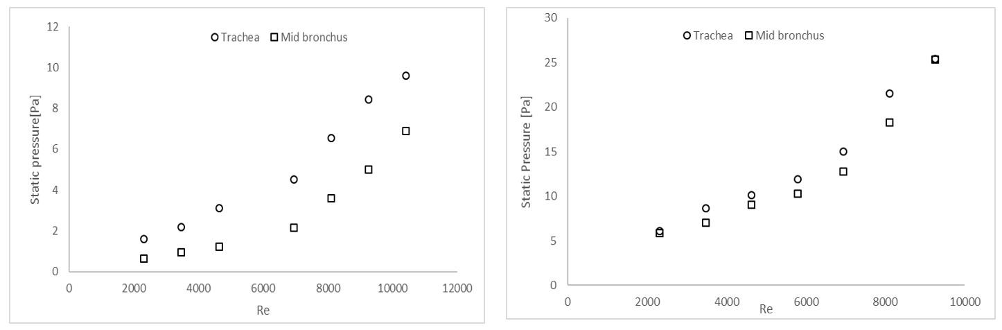
Pressure measurements for the miniature airway tree
•Static pressure is then plotted against the flow rate
•The flow rate was varied with the help of two fans
•Different flow rates were obtained by switching both the fans on (maximum flow rate), switching both the fans off (zero flow rate), switching off one of the fans and using one of the fans with obstruction
•The figure below shows that the pressure loss increases as the flow rate increased
•The pressure-flow rate relation was found to be quadratic in nature
•Further investigation is necessary for different flow condition such as fully developed or pulsatile
Pressure loss at normal (left) and constricted(right) airways
Sound measurements at the big contraction
•The hose from the fan was connected to the big contraction only
•Microphone probe were connected to the pressure tap at the exit of the big contraction
•Sound recorded at the pressure tap of the exit of the big contraction when both of the fan were on as well as when the flow was obstructed while the fans were running to quantify the noise generated from the fan motors and environment
Sound recorded at the exit of big contraction
Sound Measurement at trachea for normal and constricted airways
•A microphone was connected to the trachea in normal and constricted airways as shown in the Figure
•The sound generated at the location was measured for various flow rates
•The Fast Fourier transform (FFT) of Sound measured at the trachea for different flow was plotted which is shown in the Figure below
•Results showed that at high flow, dominant frequency varied between 60 Hz to 450 Hz, while at low flow dominant frequency was as high as 2200 Hz
Experimental setup for sound recorded at trachea and mid bronchus
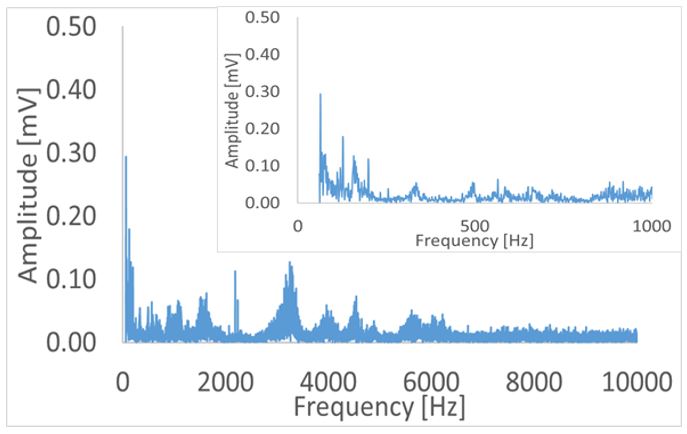
Spectral plot of noise recorded at trachea of normal airway at Re=9264. Dominant frequency 64 Hz, 2nd at 127 Hz, 3rd at 3247 Hz, 4th at 2187 Hz
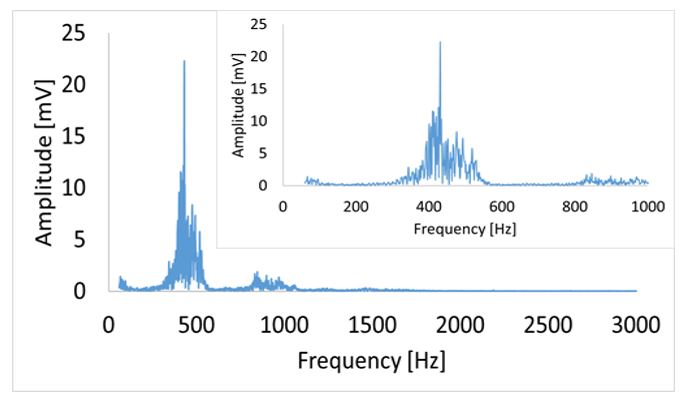
Spectral plot of noise recorded at trachea of constricted airway at Re=9264. Dominant frequency 431 Hz, 2nd at 413 Hz, 3rd at 493 Hz, 4th at 518 Hz
Discussion
•Pressure difference between trachea and mid bronchus increased as the flow velocity increased except at maximum flow, the difference reduced which is unexpected. Further investigation is needed
•Flow velocity at the trachea was calculated using flow meter which has a low resolution and cannot give reading at flow lower than 0.2 m/s. Pneumotachograph or spierometer is suggested to use instead of turbine flow meter
•Microphone is suggested to listen to the sounds to understand the nature of the sound at different location of the setup
•Use another pressure transducer to check the data from diaphragm pressure transducer
•The amplitude of the sound and the pressure loss increased for the constricted airways which is expected given the reduction of the area would lead to increase the resistance to flow
•Uncertainty calculation showed that the uncertainty in pressure measurement is abount 0.085 Pa which would lead to a velocity measurement uncertainty of about 0.07 m/s
•The flow in this study was not laminar. Hence flow needed to be reduced to study the pressure loss at laminar flow
Conclusion
•Pressure drop between trachea and mid bronchus increased at higher flow rate
•Results showed that changing flow rate would change the pressure loss as well as the sound generation in the trachea
•Sound needs to be recorded at different branch locations for normal and constricted airways
•Further investigation is necessary to evaluate different flow conditions like fully developed flow or pulsatile flow conditions